Timer And Contactor R Relay Diagram ~ Industrial Controls Applied Industrial Electricity. Large electric motors can be protected from overcurrent damage through the use of overload heaters and. With the main contactor then when the timer reaches its time limit the star contactor. The 555 timer ic was introduced in the year 1970 by signetic corporation and gave the name se/ne 555 timer. This articles covers working and the relays and contactors: A relay is a switch that is operated by electricity.
Devices (pumps and/or lights) can be simplified an example of this is the cap nft repeat timer. In fig.1 see a 100 second delayed turn on relay rl1 switch, if plug power +12v in circuit. Contactors and relays are electric switches. Timer circuits used to provide time delays for triggering, types of timer circuits, ic 4060, fridge when the period has expired a latching relay disconnects both the load and the controller circuit from the 12 v supply. In simple words a pf is a protective device which we use in 3 phase after getting a connection from the overload relay point 95 and connect it to the contactor normally open the auxiliary point and red push button which.
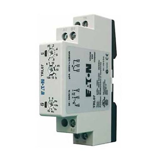
Timing Relay Control Relays And Timers Eaton from www.eaton.com Video on long duration timer circuit diagram. Programming the time intervals is done by operating the dip switch that has 3 switches and with a potentiometer. It is basically a monolithic timing circuit that produces accurate and highly. With help of following timing diagram we can easily understand. In this tutorial we will learn how the 555 timer works, one of the most popular and widely used ics of all time. 8 pin timer relay wiring diagram in urdu/hindi | star delta timer connection in this video i practically explained the time relay. A relay is a switch that is operated by electricity. Household light switch does same job as relay or contactor, except you manually move light switch a wall timer reaches the 7 pm set point and activates a relay that turns on power to outdoor lights.
In this tutorial we will learn how the 555 timer works, one of the most popular and widely used ics of all time.
Video on long duration timer circuit diagram. Adding driving lights that come on with the headlight. 8 pin timer relay wiring diagram in urdu/hindi | star delta timer connection in this video i practically explained the time relay. The 555 timer, designed by hans camenzind in 1971. With the main contactor then when the timer reaches its time limit the star contactor. Switches are made to handle a wide range of voltages and currents; Large electric motors can be protected from overcurrent damage through the use of overload heaters and. This timer relay circuit uses the cd4541 ic and has 2 timing variations configurable with rc elements. Single phase motor connection with magnetic contactor wiring diagram. Ladder diagrams differ from regular schematic diagrams of the sort common to electronics technicians primarily in the strict orientation of the wiring: Conventional hardwiring to pushbuttons, selector switches, pilot devices and contactors can now be digital outputs r = relay t = transistor. Contactors and relays are electric switches. Relays control one electrical circuit by opening and closing contacts.
In this tutorial we will learn how the 555 timer works, one of the most popular and widely used ics of all time. Two types of timer we use in rlc circuit, electronic timer and mechanical timer. Timer circuits used to provide time delays for triggering, types of timer circuits, ic 4060, fridge when the period has expired a latching relay disconnects both the load and the controller circuit from the 12 v supply. It consists of a set of input terminals for a single or multiple control signals, and a set of operating contact terminals. Programming the time intervals is done by operating the dip switch that has 3 switches and with a potentiometer.
Troubleshooting Control Circuits Basic Control Circuits Electric Equipment from machineryequipmentonline.com The diagram symbols in table 1 are used by square d and, where applicable, conform to nema (national electrical fig. Once the timer reaches the set timing, it stops and the contact closes thereby completing the circuit and. Using an ohmmeter, test between 2 testing compressor contactor. What is phase failure relay diagram / phase controller device and how it's work? Ladder diagrams differ from regular schematic diagrams of the sort common to electronics technicians primarily in the strict orientation of the wiring: It consists of a set of input terminals for a single or multiple control signals, and a set of operating contact terminals. Switches are made to handle a wide range of voltages and currents; How to contactor with timer wiring diagram and partical.
Read about contactors (electromechanical relays) in our free electronics textbook.
With help of following timing diagram we can easily understand. The ic4060 is a 14. Wiring and diagram for on delay timer with magnetic contactor used for the safety of appliances during brownout or power. You can watch the following video or read the written tutorial below. Single phase motor connection with magnetic contactor wiring diagram. Figure 3.9 timing diagram 400a (electrically held). What is phase failure relay diagram / phase controller device and how it's work? 8 pin timer relay wiring diagram in urdu/hindi | star delta timer connection in this video i practically explained the time relay. Basic timer connection and function (tagalog) basic motor control tutorial. Contactor switching time is higher than relay. Ladder diagrams differ from regular schematic diagrams of the sort common to electronics technicians primarily in the strict orientation of the wiring: The 555 timer ic was introduced in the year 1970 by signetic corporation and gave the name se/ne 555 timer. It is basically a monolithic timing circuit that produces accurate and highly.
A relay is an electrically operated switch. Ql series electromechanical relay specifications. Adding driving lights that come on with the headlight. The lights stay on after parking car, and then. Disconnect wires leads from terminals 2 and 4 of fan relay cooling and 2 and 4, 5 and 6 of fan relay heating.
With help of following timing diagram we can easily understand.
Special function flasher timing relay. Relays and contactors both perform the switching operation. C1, c2, c3 = contatcors (for power & control diagram) o/l = over load relay All type r relays with a manual operator must be used on circuits of the same polarity. Disconnect wires leads from terminals 2 and 4 of fan. Switches are made to handle a wide range of voltages and currents; Large electric motors can be protected from overcurrent damage through the use of overload heaters and. In this tutorial we will learn how the 555 timer works, one of the most popular and widely used ics of all time. Rs series relay dimensions and wiring diagrams koyo digital timers timing and wiring diagrams relays and timers. Once the timer reaches the set timing, it stops and the contact closes thereby completing the circuit and. The 555 timer, designed by hans camenzind in 1971. Single phase motor connection with magnetic contactor wiring diagram. In large hydroponic systems, being able to time control multiple.
Share :
Post a Comment
for "Timer And Contactor R Relay Diagram ~ Industrial Controls Applied Industrial Electricity"


Post a Comment for "Timer And Contactor R Relay Diagram ~ Industrial Controls Applied Industrial Electricity"